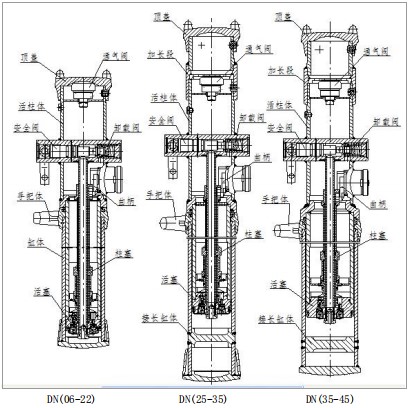


A structure this product is a mining unit hydraulic prop that is an internal liquid supply structure. It is mainly composed of top cover, vent valve, cylinder block, live cylinder, piston, hand pump, unloading valve, safety valve and handle body, among which DN25, DN28, DN31.5, DN35, DN38, DN40, The DN42 and DN45 specifications have extensions and extension cylinders. Product structure diagram: DN (06-18)-250/80, DN (20-22)-300/90 type mining hydraulic props are shown in Figure 1; DN (25 -28)-250/90, DN (31.5 -35)-160/90 type mining unit hydraulic props are shown in Figure 2; DN (35-45)-150/110 type is shown in Figure 3 DN (06-22) DN (25-35) DN (35-45)

1 Top cover

The top cover is a loaded part that is in direct contact with the top beam and is connected to the living cylinder by three elastic cylindrical pins. It has two structural forms: a. top cover, b. column cap. The top cover is used in conjunction with the metal top beam; the column cap is mainly used for the dot column, and the user can select it according to the needs. Currently, the top cover a is the most commonly used.
2 Vent valve
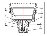
The DN-type strut is connected to the atmosphere when it is raised and lowered. When the hydraulic prop rises, the hydraulic oil in the oil chamber of the inner cylinder of the living column continuously enters the working chamber through the low pressure chamber, and the oil volume of the oil storage chamber is continuously reduced, and the gas needs to be continuously replenished, otherwise a negative pressure is formed, which affects the lifting column; When the hydraulic oil in the working chamber returns to the oil storage chamber, the gas in the oil storage chamber needs to be discharged through the venting valve, otherwise the back pressure will be formed, which will affect the falling column; when the hydraulic prop is horizontally placed, the venting valve closes itself to prevent the oil storage chamber. The oil inside leaks.

1 End cap 2 Ventilation valve body 3 O-ring seal 4 Plunger 5 Screw plug 6 Spring 7 Spool 8 Sealing washer 9 Core hammer Figure 5 Vent valve
3 Live cylinder
The living cylinder is the main bearing part of the hydraulic prop, which is welded by the assembly of the long pipe, the valve body, the core pipe, the connecting ring, the protective pipe, the living cylinder and the partition.
4 Cylinder
The cylinder block is a lower bearing part of the hydraulic prop, which is composed of a cylinder (or a long cylinder), a base sleeve, and a base.
5 Piston
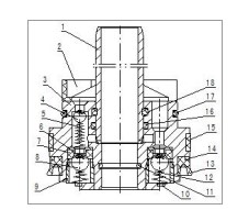
The piston acts as a live column guide and a cylinder seal. It consists of a piston head, a check valve (K1 K2), a pump sleeve, a Y-ring seal, a guide ring, an anti-extrusion ring, a filter mesh, and the like. The piston is connected to the living cylinder by screws.

1 Pump sleeve 2 Filter 3 Piston head 4 Steel ball (7) 5 Conical spring 6 Check valve limit sleeve 7 Check valve seat 8 Steel ball (10) 9 Bushing 10 Retaining ring 11 Sealing ring 12 One way Valve spring 13 Y-ring seal 14 Cup anti-extrusion ring 15 Piston guide ring 16 Seal ring 17 Seal ring 18 Seal ring
6 Hand pump
The hand pump converts the rotary motion of the crank into the linear motion of the pump piston through the crank slider mechanism, which can be divided into two stages: the primary pump has a large flow rate and a low pressure; and is mainly used for the lifting column; the flow of the secondary pump small, high pressure. The lifting column mainly relies on the first-stage pump, and the initial support mainly depends on the secondary pump. It consists of pump piston, pump sleeve, plunger, inlet valve K1, (composed of φ7 steel ball, conical spring), check valve K2 (by check valve seat, steel ball, check valve spring, lining The set consists of parts, cranks, sliders, bushings, etc.
7 Unloading valve Unloading valve for unloading of the strut. It consists of parts such as unloading valve pad, unloading valve seat, plug, and unloading valve spring.
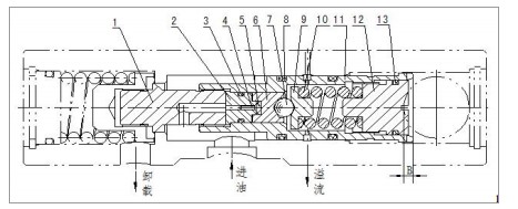
8 safety valve

1 Connecting screw 2 Seat 3 Sealing ring 4 Safety valve needle 5 Safety valve pad 6 Hexagonal guide sleeve 7 Steel ball 8 Sealing ring 9 Spring seat 10 Safety valve spring 11 Valve sleeve 12 Pressure regulating screw 13 Sealing ring Figure 7 Safety valve safety valve .The function is to prevent the hydraulic prop from being overloaded, that is, the safety valve is opened when the load of the hydraulic prop exceeds the rated working resistance, and the safety valve is closed when the load is less than the rated working resistance, so as to ensure the load at the rated working resistance during the whole working process. Small fluctuations up and down, maintaining a certain working resistance. It consists of connecting screw, valve needle, valve seat, safety valve pad, hex guide sleeve, valve sleeve, safety valve spring, pressure regulating screw and other parts. Different types of pillar safety valves have different opening pressures and the same structure.
9 Handle body
The handle body is connected to the cylinder body through the connecting wire, and can be rotated for easy operation and handling. The handle body is provided with a dustproof ring to prevent dirt such as coal dust from entering the hydraulic prop cavity.